Chladni Plates on a Commodore 64
You’ve probably seen the videos even if you didn’t know what they were called. Somebody puts sand on a metal plate and plays a tone through it (or, the old-fashioned way, drags a violin bow along the edge). The sand bounces around for a second, then gathers into lines, and the lines make a picture. Some look like diamonds or crosses, and some look like little flowers. Play a higher note, and the picture falls apart and comes back as something more complicated.
It looks like a magic trick. It’s called a Chladni plate, and people have been doing this since 1787. I’ve wanted to put one on a Commodore 64 for a while now. The SID plays the tone, sand on a virtual plate shakes off the parts that vibrate and piles up on the still lines, and when you change the pitch, the pattern rebuilds. The sound and the picture are the same thing.
I haven’t seen this done on an 8-bit machine before. Maybe it has been, and if so, send it my way. I’d love to see how they did it.
I wanted to do this one from first principles. It would’ve been easy to take photos of real plates and turn them into pixels, or to ask an AI what the patterns look like and draw whatever it said. That felt like cheating. So we start with the physics of a vibrating plate, do the math, and let the sand figure out where to go on its own. If the pictures come out looking like the ones Chladni drew, the math is right. If they don’t, something’s broken.
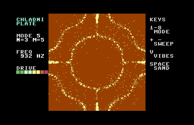
Mode 5 at 932 Hz.
We’ll go through the physics first. The code makes a lot more sense once you know what it’s faking. Then we’ll build it.
Who was Chladni?
Ernst Chladni was a German musician and physicist. He’d seen Georg Lichtenberg’s dust figures, the tree-shaped patterns you get when you sprinkle powder on an insulator after an electrical spark. Chladni wondered if sound could make pictures the same way.
So he took a brass plate, held it at one point, put sand on it, and bowed the edge. It worked. He published the results in 1787 in a book called Entdeckungen über die Theorie des Klanges (Discoveries in the Theory of Sound), and then spent years touring Europe showing people.
In 1808 he showed it to Napoleon. Napoleon was impressed enough to fund a prize from the French Academy of Sciences for anyone who could explain the patterns with math. Nobody could at first. It took Sophie Germain three tries, and she won it in 1816, the first woman to win a prize from the Academy. Her theory wasn’t quite right at the edges of the plate (literally, the edge conditions were wrong). Gustav Kirchhoff fixed that in 1850. It wasn’t until 1909 that Walther Ritz calculated the patterns for a square plate with free edges and got answers that matched what Chladni had drawn more than a hundred years earlier.
Violin makers still use this. They put glitter or tea leaves on a violin’s top plate before it’s glued up, play tones through a speaker under it, and check the patterns to see if the wood is carved right.
Start with a string
Before we get to plates, let’s look at something simpler.
Pluck a guitar string. It’s tied down at both ends, and it vibrates in the middle. Waves run down the string, hit the end, bounce back, and run into the waves coming the other way. Most of the time, they cancel each other out into a mess. But at certain frequencies, the bounced wave lines up perfectly with the incoming one, and you get a standing wave. The string looks like it’s flapping in place instead of having waves moving along it.
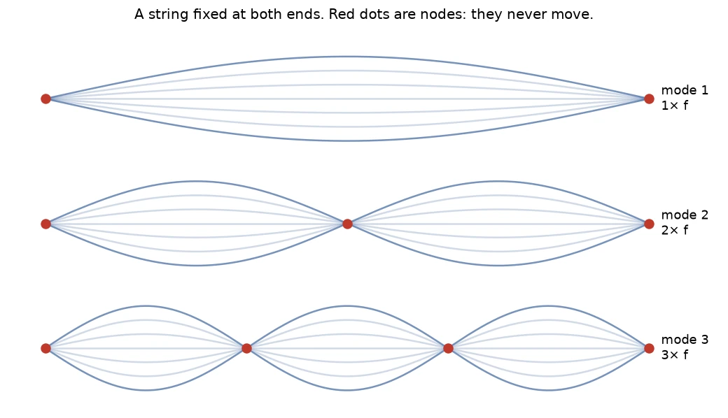
The first three ways a string can vibrate. The red dots are nodes.
The red dots are called nodes. They don’t move at all, even while the string around them is moving as fast as it can. The places in between that move the most are the antinodes.
The first mode fits half a wave on the string. The second fits a whole wave, so it’s twice the frequency, and there’s a node right in the middle. The third fits one and a half waves at three times the frequency. That’s why a string’s overtones are 1×, 2×, 3× the base note, and why a string sounds nice and musical.
If you put a tiny bit of sand on a vibrating string (good luck), it would fall off everywhere except at the nodes.
Now make it 2D
A plate is the same idea in two directions. Waves run across it left to right AND top to bottom, bounce off all four edges, and at certain frequencies they line up into a standing wave.
On a plate, the nodes are lines instead of dots, curves across the plate that hold still while everything else shakes. Sand collects on those lines, so the picture you see shows the parts of the plate that aren’t moving.
Two things make plates weirder than strings.
First, plates are stiff. A string vibrates because it’s under tension. A plate vibrates because it’s stiff, and it bends. Bending gets much harder when the bends are close together, so the frequency rises much faster as the patterns get more detailed. Halve the wavelength on a string and the frequency doubles. Halve it on a plate, and the frequency goes up four times. Roughly, the frequency goes with the square of how many wiggles you’ve got.
That’s why plate overtones aren’t nice 2×, 3×, 4× multiples, and why a struck metal plate sounds clangy like a bell instead of musical like a string. Chladni noticed this too. For round plates, he found the frequencies went up close to the square of the number of node lines. That’s called Chladni’s law.
The second thing is the edges. Chladni held his plates at the center and let the edges flap. A free edge isn’t a node. It’s usually moving. So the math for a plate is different from a drum, where the edge is clamped down tight.
The weird part: two modes at the same note
A square plate is symmetric. A pattern with 2 wiggles across and 4 wiggles down has the exact same frequency as one with 4 across and 2 down. It’s the same shape, rotated.
So when you bow the plate at that frequency, which one do you get?
You get both at once. The plate vibrates in a mix of the two, and that mix creates shapes neither one has on its own.
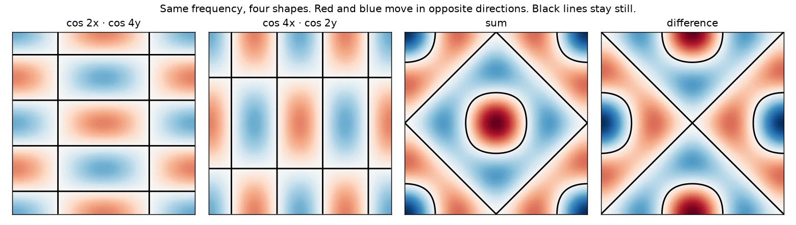
The two grid patterns on the left have the same frequency. Add them, and you get a diamond with a circle. Subtract them, and you get an X. Red and blue are moving in opposite directions, and the black lines are the nodes.
The two on the left look like boring grids. Nobody ever sees those on a real plate. Add them together, and you get a diamond with a circle in the middle, which is one of the most famous Chladni figures. Subtract them, and you get an X with curves on the sides.
Which one shows up depends on where you hold the plate and where you bow it. Wherever your fingers are touching the plate becomes a node, because your fingers stop it from moving. Chladni used this on purpose. He’d touch a spot on the edge with a finger to force a node there and pick which figure he wanted.
The formula for this mix on a square plate with free edges is roughly:
Z(x,y) = cos(n·x)·cos(m·y) ± cos(m·x)·cos(n·y)
where n and m are the number of wiggles each way, and Z is how far that spot on the plate moves. The nodes are wherever Z is zero.
This is an approximation. The exact shapes for a free square plate are messier, and that’s what took until 1909 to work out. But it’s close enough that the patterns match photos of real plates, and it’s cheap enough to compute on a C64. That’s the one we’re using.
Resonance
There’s one more piece. If you play a tone that isn’t one of the plate’s special frequencies, not much happens. The plate barely moves. Then you get close to one of those frequencies and it starts ringing, and right on it, the plate moves a LOT.
That’s resonance. Every push from the bow lands at exactly the right moment to add to the motion that’s already there, like pushing a kid on a swing at the right time. The plate stores up energy and the vibration gets big.
So as you sweep the pitch up, the plate goes quiet, rings with a pattern, goes quiet again, rings with a new pattern, and so on.
So why does the sand go to the lines?
This is the part I didn’t really get until I tried to simulate it.
There’s no force pulling the sand toward the nodes.
The plate is moving fast. Say it’s at 550 Hz and moving a twentieth of a millimeter up and down. That doesn’t sound like much, but it’s doing it 550 times a second. Work out the acceleration, and it’s around 60 g. Every time the plate swings up, it throws the grains into the air, and they land somewhere a little different.
Each grain does a random hop. The hops are big where the plate is shaking hard and tiny where it’s barely moving. On a node, the hops are zero.
So the sand wanders around at random until it lands on a node, and then it stops, because nothing there kicks it back out. Do that long enough and all the sand ends up on the nodes.
There’s a little more to it. Where the plate bends, it’s tilted, so a grain thrown off a slope tends to get thrown sideways toward the flatter, quieter parts. That speeds things up. But the main idea is just random hopping where the hop size depends on how hard the floor is shaking.
Side note: Michael Faraday noticed in 1831 that very fine powder does the opposite and collects at the antinodes. The fast-moving plate stirs up small air currents, and light powder rides them to the middle of the loudest areas. Sand is heavy enough to ignore the air.
Trying it in Python first
Before writing any assembly, I wanted to know if the physics above actually makes pictures. If it doesn’t work in Python, it’s not going to work on a C64.
This is a cleaned-up version of what I used. You’ll need NumPy and Pillow.
import random
import numpy as np
from PIL import Image

SIZE = 192           # plate is 192x192 pixels
CELL = 3             # each map cell covers 3x3 pixels
N = SIZE // CELL     # so the map is 64x64

x = np.linspace(0, np.pi, N)
X, Y = np.meshgrid(x, x)

def shake_map(n, m, sign=1):
    z = np.cos(n*X)*np.cos(m*Y) + sign*np.cos(m*X)*np.cos(n*Y)
    return np.minimum(7, (np.abs(z) * 20).astype(int))   # 0 to 7

shake = shake_map(2, 4)                  # the diamond with a circle
down_y, down_x = np.sign(np.gradient(shake))  # which way is uphill

plate = np.zeros((SIZE, SIZE), bool)     # True where there's a grain
grains = []
while len(grains) < 2048:
    gx, gy = random.randrange(SIZE), random.randrange(SIZE)
    if not plate[gy, gx]:
        plate[gy, gx] = True
        grains.append([gx, gy])

for _ in range(30):
    for g in grains:
        gx, gy = g
        cy, cx = gy // CELL, gx // CELL
        hop = shake[cy, cx]
        if hop == 0:
            continue                     # sitting on a node
        nx = gx + random.randint(-hop, hop) - int(down_x[cy, cx])
        ny = gy + random.randint(-hop, hop) - int(down_y[cy, cx])
        if 0 <= nx < SIZE and 0 <= ny < SIZE and not plate[ny, nx]:
            plate[gy, gx] = False
            plate[ny, nx] = True
            g[0], g[1] = nx, ny

Image.fromarray(plate).save("plate.png")
shake_map is the formula from earlier. It turns how hard each spot shakes into a number from 0 to 7, which is how far a grain sitting there can hop. np.gradient works out which way the shaking gets stronger, and every hop gets nudged one pixel the other way. That’s the tilted plate from a minute ago.
The rest is random hopping. Grains on a node don’t move, and a grain stays put if its hop would land it off the plate or on top of another grain.
Thirty passes later:
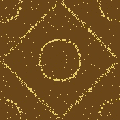
The Python version after 30 passes.
That’s the diamond with a circle from the mode-mixing picture, and nothing in the code says where the lines go.
The prototype I actually used was uglier. It copied the C64’s integer math exactly, with the same cosine table and the same rounding, so I could compare its maps to the C64’s byte for byte. That came in handy when I hit a bug on the C64.
You didn’t think we’d skip the Commodore, did you?
This turns into a pretty nice list of jobs for a C64:
- Play a tone on the SID.
- Figure out how hard each spot on the plate shakes at that tone.
- Move a bunch of sand grains around at random, with bigger hops where it’s shaking more.
- When the pitch changes, switch to a new shake map and let the sand sort itself out again.
Why not BASIC?
Usually I’d start in BASIC and then do an assembly version. This time I went straight to assembly, because the whole point here is watching the sand move.
BASIC has COS, so the math would be easy to write. But BASIC does everything in floating point, and on a 1 MHz machine that’s slow. Moving one grain means a few lookups, some address math to find the right byte in the bitmap, a PEEK to see if the spot is free, and a couple of POKEs.
I wanted real numbers, so I wrote a BASIC version anyway and timed it with TI. I tried to be fair to it. Every bitmap address and bit mask comes from a lookup table, and the cosines are worked out once per row and column instead of once per cell.
| Job | BASIC | Assembly |
|---|---|---|
| Build one shake map | 9 minutes | under 1 second |
| Sprinkle 2048 grains | 2 minutes 19 seconds | instant |
| One pass over the sand | 3.5 to 5.5 minutes | a fraction of a second |
Ten passes took 44 minutes, and the pattern was still fuzzy. Building all 8 maps would take over an hour before the first grain moves. Add the passes, and you’re looking at a couple of hours for one sharp diamond.
The BASIC version also gave me a new bug. I had G=GOR32 in there, meaning G OR 32. The tokenizer saw GO (as in GO TO) first and threw a ?SYNTAX ERROR. Spaces matter sometimes.
The catch is that the 6502 itself doesn’t have cosines. It doesn’t have multiply either. It can add, subtract, and shift, and that’s about it. So the math has to be turned into something it CAN do.
Step 2 is the expensive one, because it’s cosines and multiplies. So we do it ahead of time. At startup the C64 builds a “shake map” for 8 different modes and keeps it in memory. While the sand is running, it’s all table lookups.
Here’s the layout:
| What | Size | Where |
|---|---|---|
| Code and tables | 5.5K | $0801-$1daf |
| Hires bitmap | 8K | $2000-$3fff |
| 8 shake maps | 32K | $4000-$bfff |
| Font copy and scratch | 1K | $c000 |
| Grain X and Y | 4K | $e000-$efff |
The plate is 192×192 pixels in the middle of a high-res bitmap screen, with 2048 grains of sand. Each grain is one pixel.
192 is a handy number here. The plate starts at pixel 64 on the screen, so a grain’s screen X is its plate X plus 64, and 191 + 64 = 255. It fits in one byte. We’ll use that trick again in a minute.
We’re not going to go through every line. Here are the interesting and difficult parts.
Cosines without multiplying
Each map is 64×64 cells, one byte per cell, and each cell covers a 3×3 pixel patch. For every cell we need:
cos(n·x)·cos(m·y) ± cos(m·x)·cos(n·y)
That’s two multiplies per cell, 4096 cells per map, 8 maps. On a 6502 with a shift-and-add multiply, that’s a long wait.
But there’s an old trig identity:
cos(a)·cos(b) = ( cos(a+b) + cos(a-b) ) / 2
A multiplication of two cosines turns into two cosine lookups and an addition. Adding angles is easy if you measure them the right way.
So we measure angles in 256ths of a circle instead of degrees. A full circle is 256, so angles wrap around automatically when the byte overflows. The cosine table is 256 bytes, with values from -31 to +31:
costab: .fill 256, round(31*cos(toRadians(i*360/256))) & $ff
I picked 31 so four of them can’t overflow a signed byte. 4 × 31 = 124, which still fits.
Now each cell is four lookups:
        lda colN+1          ; cos(nx+my) + cos(nx-my)
        clc
        adc rowM+1
        tay
        lda costab,y
        sta acc
        lda colN+1
        sec
        sbc rowM+1
        tay
        lda costab,y
        clc
        adc acc
        sta acc
…and the same again for the other half, then add or subtract the two halves depending on which mix we want.
colN is n·x and rowM is m·y, both kept as 16-bit numbers. Each time we move one cell to the right, we add a fixed step to colN, and the top byte is the angle we use. The step is n × 32768 / 63, worked out by KickAssembler when it builds the program, so x goes from 0 to half a circle across the 64 cells. That’s how many half-waves fit across the plate.
That’s an add per cell instead of a multiply. Clear as mud? It’s the same thing a DDS chip does to make sine waves, just in two directions.
Then we take the absolute value, because we only care how hard a spot shakes, not which direction it’s going.
Building all 8 maps takes about 7 seconds. That’s a long time to stare at a blank screen, so I gave it something to do. While each map builds, the SID plays that mode’s tone, and when it’s done, the node lines flash up on the plate as dots.
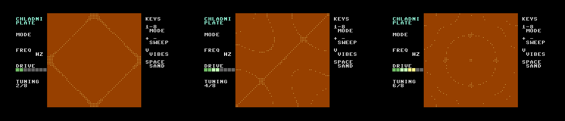
Tuning. Each mode plays its tone while its map is built, then shows its node lines.
It sounds like the plate is warming up. I like it a lot more than a progress bar.
What’s in a map byte
The first version of the map just held how hard each cell shakes, from 0 to 7. Each grain looked up its cell and took a random hop of up to that many pixels in each direction. That’s exactly the physics from earlier.
My first Python try didn’t have the downhill nudge. It worked, but it was slow.
Random hops don’t get a grain very far very fast. To wander 20 pixels away by random hops of 4 pixels, you need about 25 hops on average, and some grains take a lot more. The patterns took forever to show up.
Remember the tilted plate? Where the plate bends, sand gets thrown downhill toward the quieter parts. That’s the nudge in the Python code above. When building the map, the C64 compares each cell to its neighbors left and right, and up and down, and works out which way is “downhill” toward less shaking. Every grain gets a one-pixel nudge that way on every hop, on top of the random part.
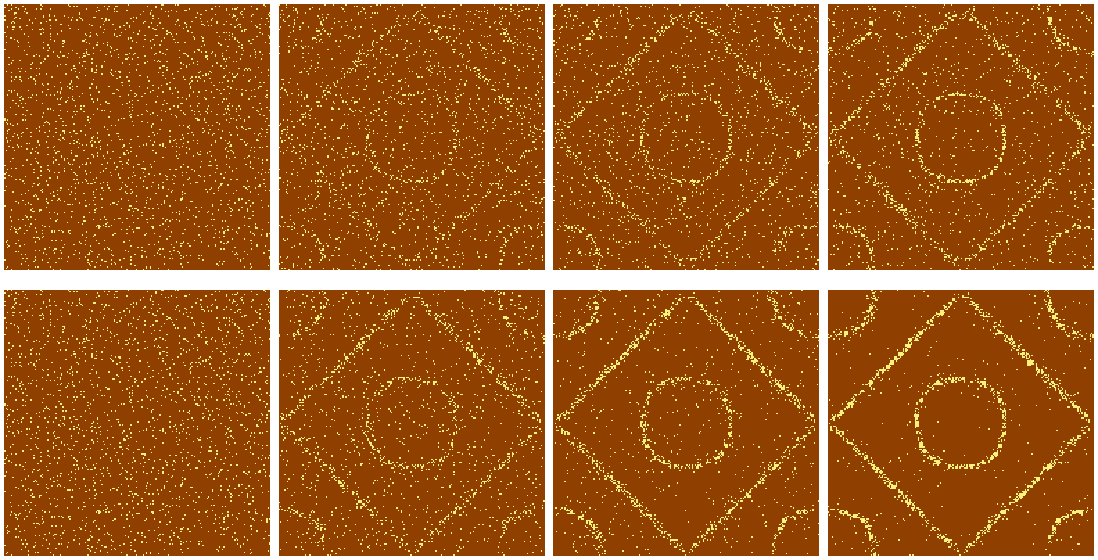
Python prototype after 0, 5, 10, and 20 passes. Top: random hops only. Bottom: random hops plus a one-pixel nudge downhill.
Same number of passes, MUCH sharper lines.
Now each map byte holds three things:
bit:   7   6 5      4 3      2 1 0
       -   y-drift  x-drift  shake level
The drift is 0 for none, 1 for +1 pixel, 2 for -1 pixel. That’s 7 bits, so 128 possible map bytes.
The grain loop doesn’t decode that byte. It uses it as an index into two little 128-byte tables, rowx and rowy, that point at the right row of a step table. Each row of the step table is 8 possible moves for that shake level and drift. Pick one of the 8 at random and that’s the hop.
The “how loud is the plate” knob is in those two tables too. That comes up again in the pitch section.
The grain loop
This is where the C64 spends nearly all its time. For each of the 2048 grains:
- Look up its cell in the current map.
- If the shake is zero, skip it. It’s sitting on a node.
- Pick a random hop for x and for y.
- If the new spot is off the plate or already has a grain in it, skip it.
- Otherwise, erase the old pixel and draw the new one.
Step 4 has two neat tricks in it.
The first is that one compare checks both edges. Plate X goes from 0 to 191, and a hop goes from -8 to +8. Add them:
        lda steptab,y       ; dx, -8 to +8
        clc
        adc ox              ; old x
        cmp #192            ; off the plate on either side when >= 192
        bcc !+
        jmp next
If the grain goes off the right side, the result is 192-199. If it goes off the left side, it goes negative and wraps around to 248-255. Both are 192 or more. One CMP catches both edges.
The second is that I don’t keep a separate grid of where the grains are. The bitmap already knows. If the pixel is on, there’s a grain there:
        ldy nx
        lda mask,y          ; which bit in the byte
        sta nmask
        ldy #0
        and (ptr),y         ; is that pixel already lit?
        bne next            ; a grain is already there
        lda (ptr),y
        ora nmask
        sta (ptr),y         ; draw the grain in its new spot
Since two grains can’t share a spot, sand that lands on a node line has to stack up next to the grains already there. The lines get thicker as more sand arrives, just like the real thing. It also handles “the grain didn’t move” for free. If the hop is 0,0, the target pixel is the grain itself, which is lit, so it skips.
On a stock C64, a pattern shows up about 2 to 3 seconds after the sand drops and is sharp in about 7.

Mode 4 forming on the C64, from the sand dropping to about seven seconds later.
Is the SID random enough?
I wanted the SID to shake the sand for real, not just play the sound. The SID’s voice 3 can play noise, and you can read its output at $D41B. Turn the volume off for voice 3 and you’ve got a free hardware random number source. People have used this trick since the 80s.
So the first version used one read of $D41B per grain. Low 3 bits for the x hop, next 3 for the y hop.
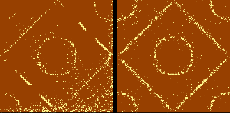
Left: SID noise as the only random source. Right: fixed.
Uhhh. That’s not right.
The diamond and circle are there, but diagonal streaks run across the plate, and sand piles up along the bottom edge. Those are the random numbers.
The SID’s noise generator is a shift register. Every so often, it shifts its bits over by one and feeds a new bit in. The byte you read at $D41B is 8 bits picked from different spots in that register. Two problems:
- The x hop and the y hop come from the same byte, so they’re related. When one goes one way, the other tends to go a certain way too. Grains drift diagonally.
- My reads are only a hundred-ish cycles apart. In that time, the register only shifts a few times, so each read is partly a shifted copy of the last one.
We’ve been here before. The C64’s RND has its own problems, and it turns out SID noise isn’t a great random source when you need thousands of numbers a second.
The fix is a 16-bit xorshift, a tiny pseudo-random generator that’s about 30 cycles on a 6502:
        lda xs+1            ; 16-bit xorshift
        lsr
        lda xs
        ror
        eor xs+1
        sta xs+1
        ror
        eor xs
        sta xs
        eor xs+1
        sta xs+1
        eor $d41b           ; mix in SID voice 3 noise
        sta rnd
That fixed it completely. The right side of the picture above is the result.
But look at the second-to-last line. I still mix the SID noise in. Didn’t I just say it was the problem?
This is the XOR magic from the cipher series. XOR flips bits. Each output bit is the xorshift bit, flipped if the SID bit is a 1. If the xorshift bit is a fair coin flip, 50/50, then flipping it or not flipping it is still 50/50. It doesn’t matter how lopsided or patterned the SID bit is. The output can’t get any worse than the xorshift on its own. It can only get more unpredictable.
That only works if the two sources aren’t related to each other. One is math, and the other is a separate chip, so we’re OK.
The SID noise only goes into the output, never back into the xorshift’s state, so the generator keeps its full run length. It costs 4 cycles per grain.
The bug that drew the wrong picture
This one cost me some time.
Modes 1 through 4 looked great. Mode 5, which should be a circle with a cross through it, drew a plain diamond. Modes 6, 7, and 8 did too. They all looked like mode 1.
The startup preview showed every map building correctly, so the maps were fine. I pulled all 32K of maps out of VICE’s memory over its remote monitor and checked them byte by byte against the Python version. Every byte matched.
But the variable holding the current map’s address was wrong. Mode 5’s map lives at $8000, and the variable said $4000.
Here’s the code that works out which map to use. Mode 0 is at $4000, mode 1 at $5000, and so on:
        lda pmode,x         ; mode 0-7
        asl
        asl
        asl
        asl                 ; x16: mode 4 becomes $40
        ora #>MAPS          ; + $40
        sta mapbase
See it? I used ORA to add $40. That works as long as the two numbers don’t have any bits in common. Mode 3 is $30, and $30 OR $40 is $70. Fine. Mode 4 is $40, and $40 OR $40 is… $40. Not $80. It landed right back on mode 1’s map.
I know ORA isn’t addition. I did it anyway.
        clc
        adc #>MAPS
Adding the CLC and using ADC fixed it. All 8 modes work now.
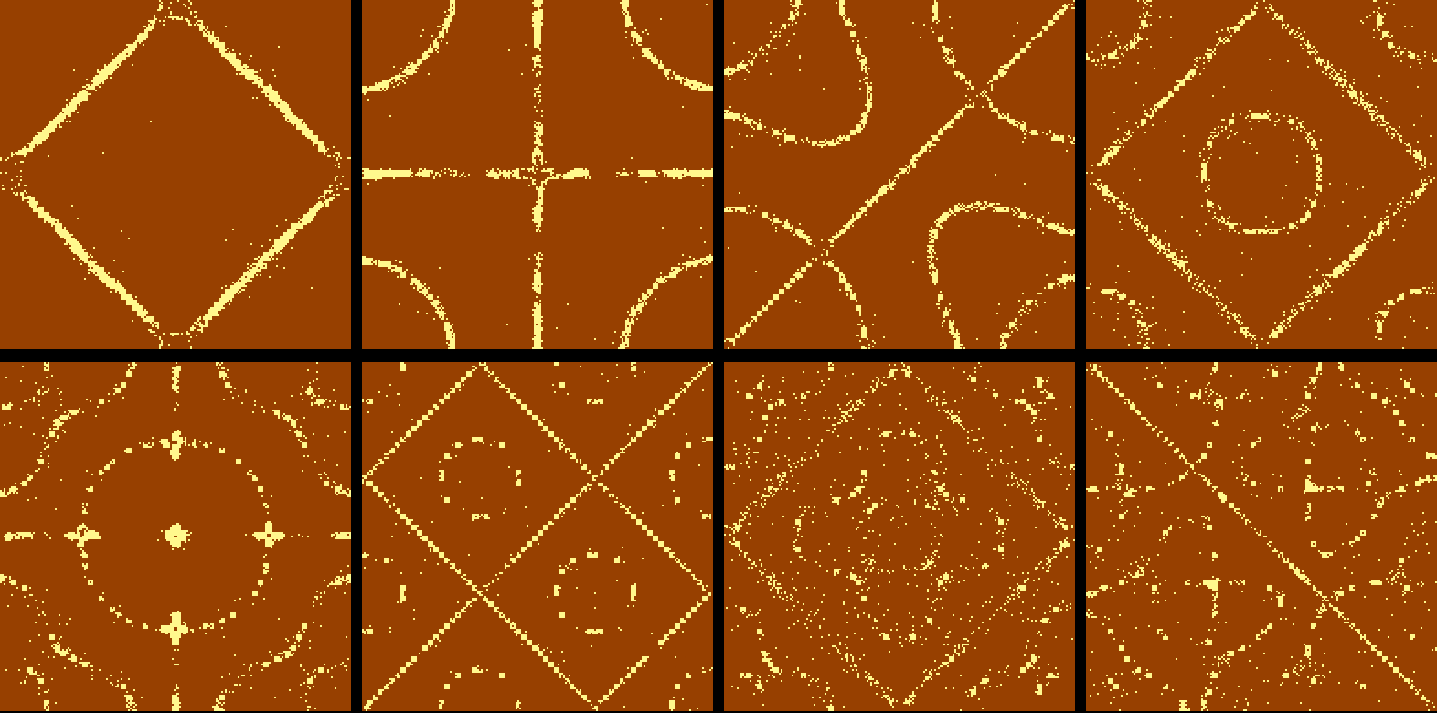
All eight modes, from 110 Hz up to 1812 Hz.
The top row is nice and clean. The bottom row is more detailed, and with only 2048 grains, the finest ones are a little grainy (ha). A real plate has millions of grains.
Sweeping the pitch
The number keys jump straight to each of the 8 modes. The plus and minus keys, or the cursor key, sweep the pitch up and down in quarter tones.
Each mode’s frequency goes up with n² + m², like a stiff plate. I set the first one to 110 Hz so you can hear it. The real numbers would depend on the plate’s size, thickness, and what metal it’s made of.
As you sweep, the program works out how far you are from the nearest mode. Right on it, the plate rings at full strength. A quarter tone off, it’s down to about three-quarters. Four quarter tones off, nothing. The plate goes quiet, and the sand just sits there.
That’s where the rowx and rowy tables come in. When the pitch changes, a routine in the interrupt rebuilds them with the shake levels scaled down. The grain loop doesn’t change at all. It does the same lookups and gets smaller hops. When the level drops to zero, the grain doesn’t move.
The volume follows it too. The SID gets louder right on a resonance and softer between them. It’s not really how a speaker driving a plate works, but you can hear the plate “catch” the note, and that matches what’s happening on screen.
Press V and the plate turns into a map of how hard each part is shaking.
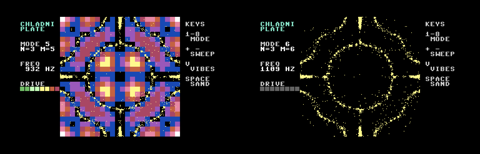
Left: the vibration overlay on mode 5. The sand is sitting in the black, the parts that don’t move. Right: swept off the resonance. The plate goes dark, and the sand freezes.
The overlay is worked out fresh from the cosine formula at the center of each 8×8 character cell, then turned into a color in color RAM. It doesn’t use the shake map, because that tops out at 7, and nearly everything comes out bright yellow. Computing it directly gives a nice smooth ramp.
Where’d the KERNAL go?
The code and tables ran a few hundred bytes past $2000, right into the bitmap. Turning off the KERNAL ROM frees up the RAM under it at $e000, so the grain arrays moved there. That means I had to write my own keyboard scan in the interrupt, but it’s only about 50 lines, and it only looks for the keys I care about. It also gives the grain loop a little time back, since the KERNAL isn’t doing its thing 60 times a second.
Why brown and yellow?
I tried white sand on a black plate, like most photos. I tried a few other colors. A brown plate with yellow sand won by a mile. It looks like a brass plate under a warm light, which is what Chladni would’ve used.
The best part is sweeping the pitch slowly and watching it happen. The sand sits still between notes, then the plate catches a resonance, the SID gets louder, and the grains start running for the lines. You have to go slowly, though. The jump from one resonance to the next is quick, and it’s easy to skip right past one.