Blinkenlights
By Michael Doornbos
- 7 minutes read - 1480 wordsIn the world of tech, including vintage tech, the lure of the blinkenlight is strong.
And if you don’t like blinkenlights, can we even be friends?
My PiDP-8 might be the ultimate in blinkenlight flexing, BUT we can probably do some other fun stuff if we use math. And science!
Vicarious excitement is not as good as the real thing, he finds. - Cryptonomicon Neal Stephenson, 1999
Let’s make some 8 bit computer equipment output some stuff “in the real world” shall we?
The players
We will work with the Commodore VIC-20 and my KIM-1 clone, the PAL-1. We’ve used my other clone, the Corsham KIM-1 in the past, and the concepts should be the same for most KIM-1 machines.
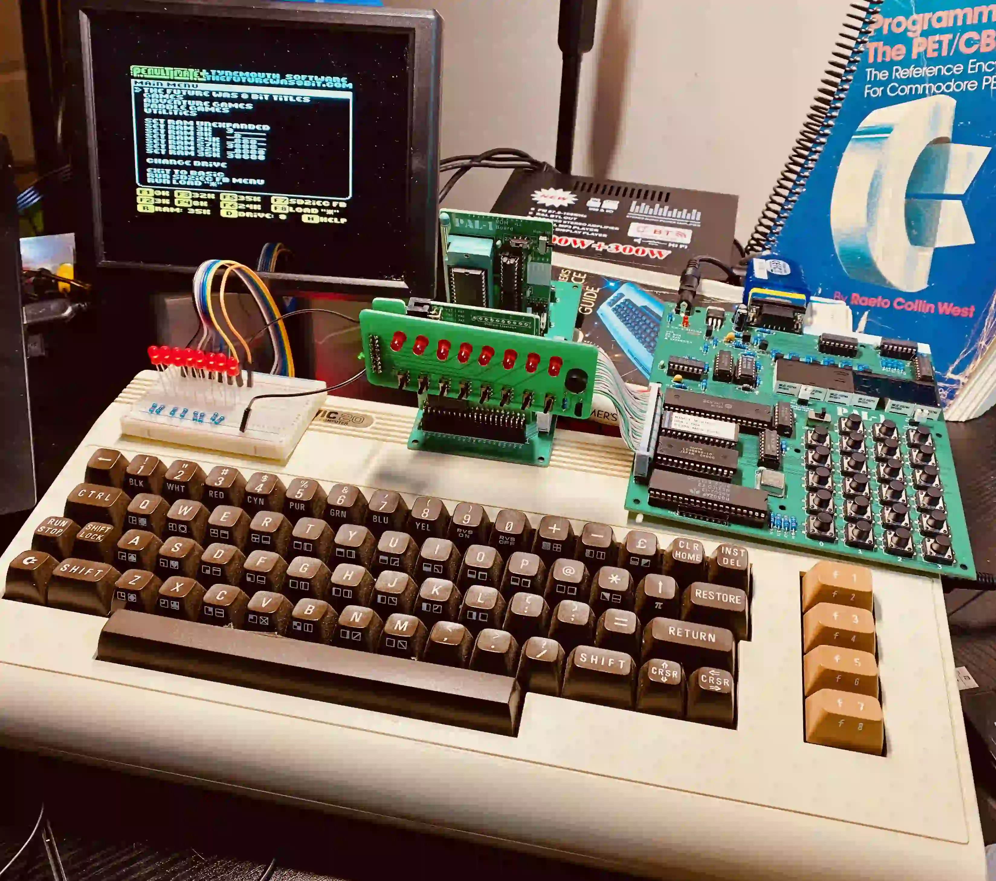
The VIC-20 and the Commodore 64 share the same USR port layout. These examples will work on both with simple changes to memory locations. Check out Mapping the C64 for more details on the C64 locations.
Caveat
This is one of those times where you will need an actual vintage machine (or clone) to do these yourself. If there’s a way to do USR port stuff in an emulator, please drop me a line on how to do that so we can point folks in the right direction.
Simple count up and down
The way the USR port works is to set a direction of input or output and then you can read or set a single byte from a memory location to work with 8 of then pins at once. We’ll be using PB0-7 on both the VIC-20 and the PAL-1.
VIC-20/BASIC Version
First, let’s just count up by ones. This will show us a nice binary count on our LEDs.
LED Setup
The USR port on the VIC-20 is very straighforward. Keep in mind that you’re connecting directly to the VIA chip (#2) so do use some care in connecting everything corretly. The port pins are:
  GND  +5   RST PA2  PA3  PA4  PA5  PA6        +9   +9   GND
|----|----|----|----|----|----|----|----|----|----|----|----|
   1    2    3    4    5    6    7    8    9   10   11   12

   A    B    C    D    E    F    H    J    K    L    M    N
|----|----|----|----|----|----|----|----|----|----|----|----|
  GND  CB1  PB0  PB1  PB2  PB3  PB4  PB5  PB6  PB7  CB2  GND
Yes, they did skip I in the lettering. If someone knows why, I’d like to hear about it
I happen to have a very nice breakout board to access the USR port easily.
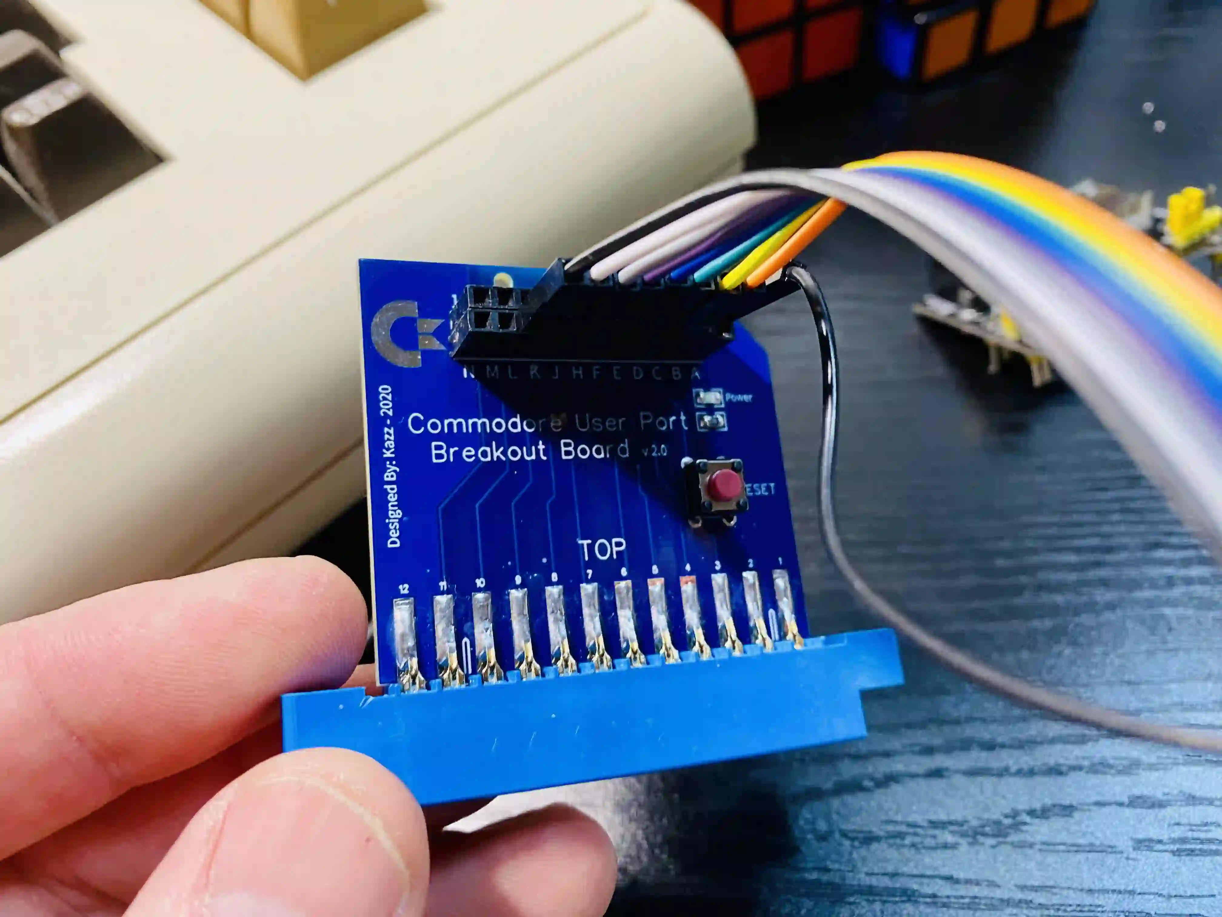
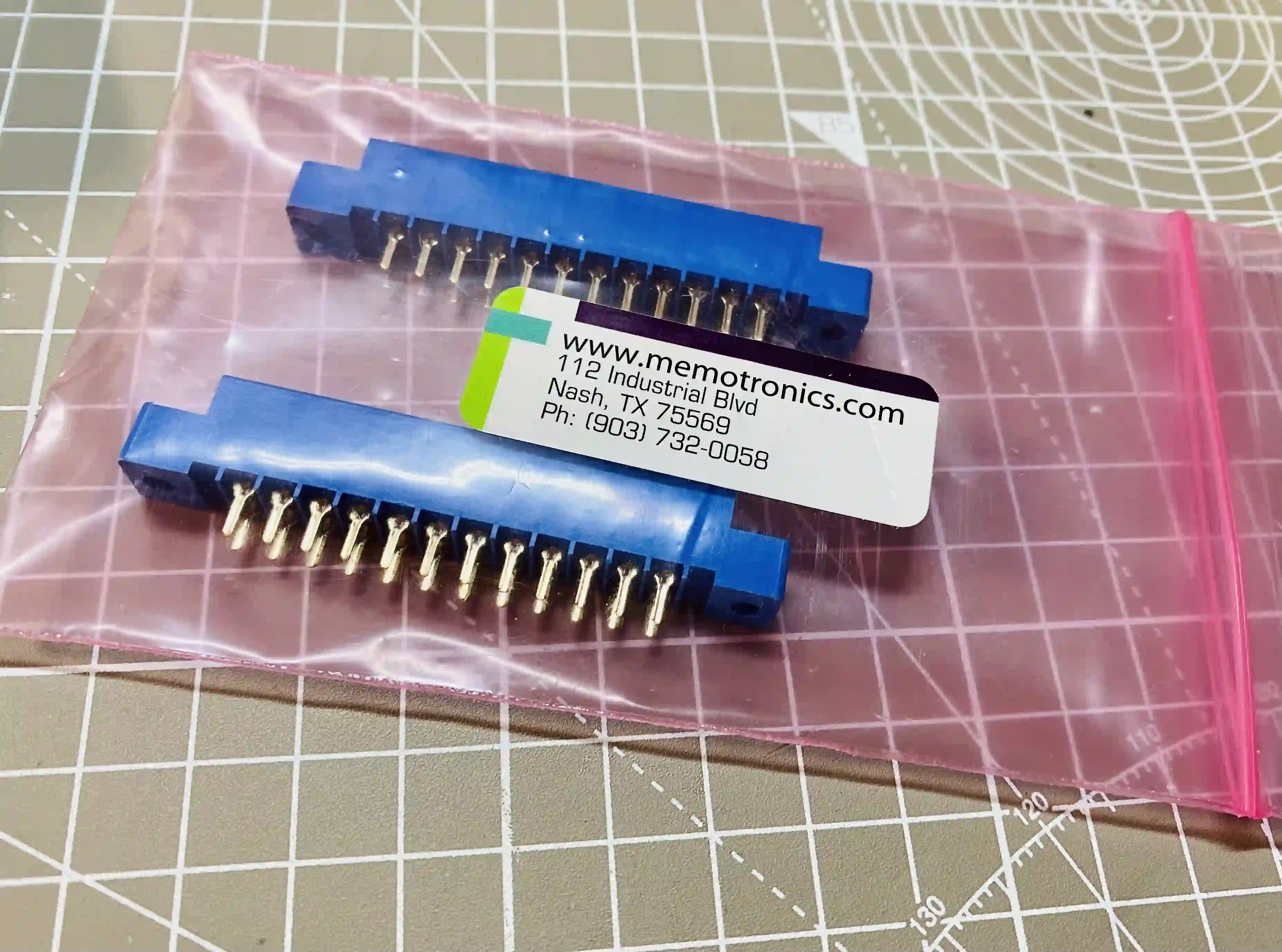
The edge connectors for these ports are still available on the interwebs if you wanted to build your own connector for this experiment.
The LEDs are powered directly by the VIA (VIA-2 in this case) on the VIC-20 and the RIOT Chip on the KIM-1 Clone.
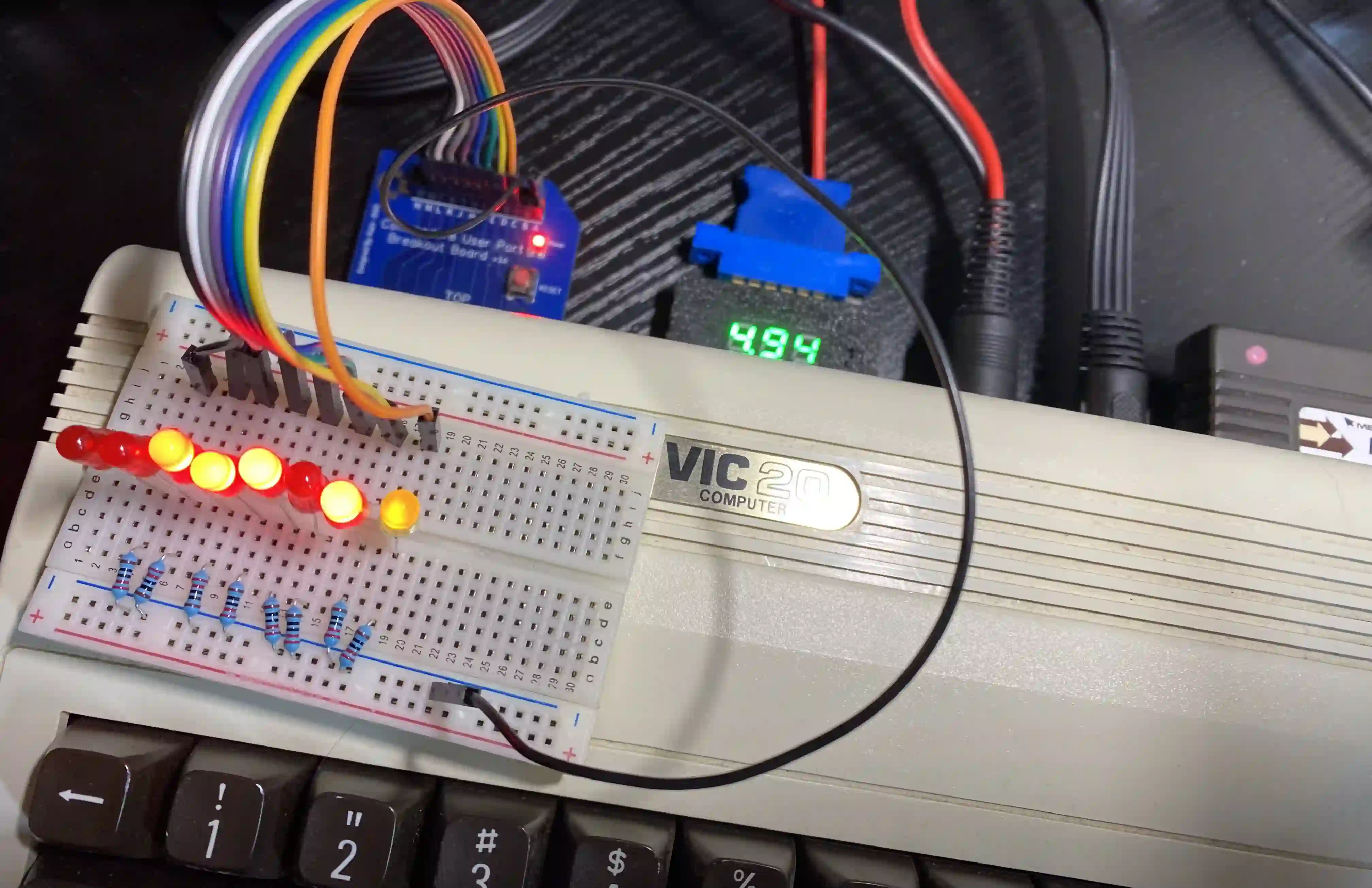
I’ve connected the ports PB0-PB7 to the positive side of 8 LEDs and connected the negative side through some resistors and back to ground.
Driving 8 LEDs from the user port is fine, but for anything that might require more power, be sure to power those things from an external source.
BASIC Code
This is pretty straightforward. We’re just going to count from 1 to 255 and set that value to memory location 37136.
But first, we’ll set location 37138 to make all 8 pins output pins by poking 255.
5 REM COUNT UP
6 REM VIC-20 BLINKENLIGHTS
10 POKE 37138,255: REM C64 56579
20 POKE 37136,1: REM C64 56577
30 I=I+1:IFI>254THENI=1
40 POKE 37136,I
50 FORJ=0TO100:NEXT:REM DELAY
60 GOTO 30
Then on lines 30-40 we just loop through 1 to 255 and poke that value into the register. This will have the effect of lighting up the binary value of what we poke here on our 8 LEDs.
On line 50 we waste a little time to slow it down. Play with the values here to speed it up or slow it down.
KIM-1
LED Setup
It shouldn’t be a surprize that the VIC-20 (and all of the Commodore 8-bits) gets this PB direction functionality from the KIM-1, which came years before it.
The PB registers on the KIM-1 are $1703 for the direction and $1702 to set the bits. Otherwise, the functionality is the same.
I’m using the PAL-1 LED gadget which is available from the creator of the PAL-1.
Assembly Version
While we certainly CAN load Microsoft BASIC or even TinyBASIC on the KIM-1 clone, the code would be almost idential to the VIC-20 version. The only difference being the two memory location changes.
Let’s do this one in Assembly.
I usually do assembly “on hardware” rather than use a modern assembler. PBUG is my KIM-1 weapon of choice for this. Feel free to use whatever you want, but you get bonus points for doing it on graph paper by hand then then entering it via the keypad. Just an idea.
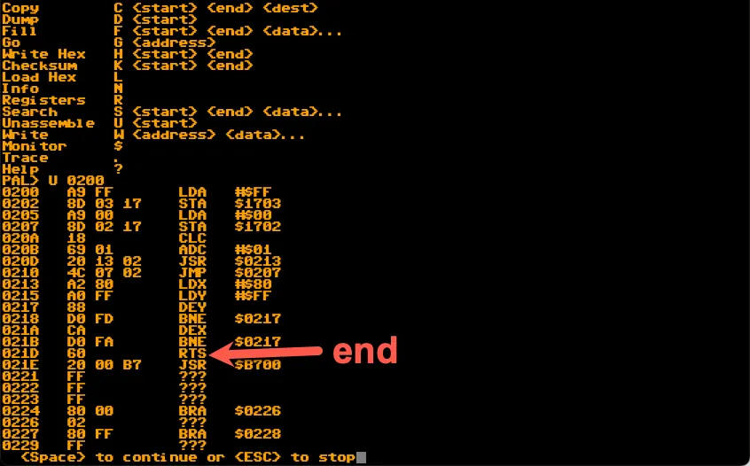
PAL> U 0200
0200   A9 FF       LDA   #$FF
0202   8D 03 17    STA   $1703
0205   A9 00       LDA   #$00
0207   8D 02 17    STA   $1702
020A   18          CLC
020B   69 01       ADC   #$01
020D   20 13 02    JSR   $0213
0210   4C 07 02    JMP   $0207
0213   A2 80       LDX   #$80
0215   A0 FF       LDY   #$FF
0217   88          DEY
0218   D0 FD       BNE   $0217
021A   CA          DEX
021B   D0 FA       BNE   $0217
021D   60          RTS
This is exactly the same as our BASIC version (no really!). If you’re an assembly novice, let’s break it down a little. Note that these values are in hexidecimal.
We load the accumulator with $FF and store it in $1703. This is the same as our POKE 37138,255 on the VIC-20.
Then we store $00 in $1702 and start looping, adding 1 each time we loop. The JSR at memory location $020D jumps to $2013 which is a way to introduce a delay by making the processing count the X and Y registers a bunch of times.
This delay is even more important in the assembly/machine code version, because without it the lights would blink so fast they’d appear to be on all the time. We’re doing this for the visual effect.
Results
Pretty neato.
Shift lights… You know, the Cylon motion
Okay, now it’s time for the “Cylon” light shifting. Or maybe KIT from Knightrider? I’m good with either.

VIC-20/BASIC Version
Here we do much the same as before with two changes.
5 REM COUNT UP AND DOWN
6 REM VIC-20 BLINKENLIGHTS
10 POKE 37138,255: REM C64 56579
20 POKE 37136,1: REM C64 56577
30 D=1:REM DIRECTION
40 I=1
50 IFI>127 OR I<2 THEND=D*-1
60 IFI=0THENI=1
70 IF D=1THENI=INT(I*2)
80 IF D=-1THENI=INT(I/2)
90 POKE 37136,I
100 FORJ=0TO100:NEXT:REM DELAY
110 GOTO 50
On line 30 we set a direction flag so we know which way we want it to rotate.
On line 40 we do the check for when to flip the direction.
On line 70 we multiply by two if the flag is 1.
On line 80 we devide by two if the flag is -1.
The effect we’re looking for is to make one light to the left (then the right) light up.
So we’re lighting up 1,2,4,8,16,32,64,128. Then we start dividing down: 64,32,16,8,4,2,1. Repeat.
In binary that would look like:
00000001
00000010
00000100
00001000
00010000
00100000
01000000
10000000
KIM-1 Assembly Version
We’ll do almost exactly the same thing for the assembly version. Again using a delay loop starting at $023D to slow it down so we can watch it work.
00B4 20 B400
PBUG for the PAL-1
PAL> U 0200
0200   A9 FF       LDA   #$FF
0202   8D 03 17    STA   $1703
0205   A9 01       LDA   #$01
0207   8D 02 17    STA   $1702
020A   85 00       STA   $00
020C   A5 00       LDA   $00
020E   F0 11       BEQ   $0221
0210   20 3D 02    JSR   $023D
0213   AD 02 17    LDA   $1702
0216   2A          ROL   A
0217   8D 02 17    STA   $1702
021A   C9 80       CMP   #$80
021C   F0 15       BEQ   $0233
021E   4C 3A 02    JMP   $023A
0221   18          CLC
0222   20 3D 02    JSR   $023D
0225   AD 02 17    LDA   $1702
0228   6A          ROR   A
0229   8D 02 17    STA   $1702
022C   C9 01       CMP   #$01
022E   F0 03       BEQ   $0233
0230   4C 3A 02    JMP   $023A
0233   18          CLC
0234   A5 00       LDA   $00
0236   49 01       EOR   #$01
0238   85 00       STA   $00
023A   4C 0C 02    JMP   $020C
023D   A2 80       LDX   #$80
023F   A0 FF       LDY   #$FF
0241   88          DEY
0242   D0 FD       BNE   $0241
0244   CA          DEX
0245   D0 FA       BNE   $0241
0247   60          RTS
There are quite a few ways we could do this differently. Since we’re slowing it down on purpose, spending a lot of time on making it faster doesn’t make much sense, but if you enjoy that sort of problem solving, knock yourself out.
So how’d we do?
Looks great!
Extra credit
Implement this on differnt 8 bit computers that have USR ports and let me know how you did!
Caution, the USR port on the Commodore PET has a slightly different layout, be careful.